Crane duty motors
- D = Starting
- N = Operating under rated condition
- F = Electric braking
- R = At rest & de-energised
- 0max = Maximum temperature attained during the duty cycle
- 1. Crane Duty & Hoist duty application Including LT and CT drives
- 2. Material Handling
- 3. Weirs and Sluices
- 4. Lift Duty
- 5. Auxiliary motors in rolling mills
- Duty Operation of the motor at load including no load & de-energised period to which the motor is subjected including the sequence & duration.
- Cyclic Duration Factor (CDF) The ratio between the period of loading including starting & electric braking and the duration of the duty cycle expressed as percentage.
- Starting The process of energizing a motor to bring it upto its rated speed from rest.
- Electric Braking A system in which a braking action is applied to an electric motor by causing it to act as a generator.
- Regenerative Braking A system of electric braking in which energy is returned to the supply system.
- D C Injection Braking A form of braking of an induction motor in which a separate DC supply is used to magnetise the motor.
- Plugging A form of braking of an induction motor obtained by reversing the phase sequence of its any two lines.
- F = Maximum total load in Kg
- V = Hoisting speed in mtrs/sec
- Eff = Overall mechanical efficiency of the driving unit.
- M = Torque required for movement in Kgm
- n = Motor RPM
Suppliers, Distributors, and Exporters of Crane Duty Motors
Aakash Power is a Global Supplier, Exporter, and Distributor of Crane Duty Motors, delivering complete motor solutions to the world’s most demanding industries. Our Crane Duty Motors are approved by the international set of standards.
INTRODUCTION
TEFC squirrel cage induction motors specifically designed for DOL operated Crane duty / intermittent duty application. The motors are designed to take care of the high electrical and mechanical stresses arising due to frequent starts - stops associated with intermittent duty application. The motors are compact providing high output for a given frame size and have low inertia. These salient features make them most suitable for EOT Cranes.
RANGE
| KW | 0.18 to 45.0 kW |
| RPM | 1500, 1000, 750 |
| Mounting | Foot (B3), flange (B5), face (B14) & combinations |
| Frame | 71 to 355L |
| Voltage | 415V ± 10% or as required |
| Frequency | 50Hz ± 5% or as required |
| Ambient | 40°C. |
| Altitude | upto 1000m above m. s. l. |
| Rotor type | Squirrel cage aluminium die cast |
| Enclosure | Totally enclosed fan cooled (TEFC) |
| Protection | IP55 |
| Insulation class | Class F insulation with temp. rise limited to class B |
| Duty cycle | S2 – S5 |
| Standards | IS: 325, IS: 1231, IS: 2223 & IS: 4722 |
CONSTRUCTION
Frame
The stator frames in general are made of rugged cast iron with integral cast feet in case of foot mounted motors. Maximum cooling surface is obtained by quadrangular disposition of cooling ribs.
End Bracket
Ribbed end brackets are provided from frame 160 upwards. For frame sizes upto 225S, single piece end bracket is eliminating outer bearing cap. For frame sizes 200L and above, unique feature of grease relief arrangement facilitating on-line re-greasing is provided.
Shaft
Standard motors have single cylindrical shaft extension. However, double cylindrical shaft extension or tapered shaft extension (single / double) can be offered on request.
Terminal Box
The terminal box position of all the motors are on RHS when viewed from the driving end except for 71 frame & 112M frames. The terminal box position for these frames is on TOP only. Terminal box for all the motors can be rotated in steps of 90° through 360° – there by providing four alternative direction of cable entry.
Bearings
Metric size ball / roller bearings with C3 clearance are used in horizontal foot mounted motors. For frame sizes upto 315L, ball bearings are used at both ends whereas for frame size 355 – roller / ball bearings are used on DE/NDE side respectively. Double shielded bearings are used upto frame 180. These bearings are pre-lubricated and do not allow re-lubrication. Grease used for motors of frame 200 onward is Alithex 20 or equivalent [Lithium based grade 2]
Cooling and Degree of protection
Motors have cooling arrangement as per IC411 (TEFC) in accordance with IS:6362. The degree of protection of standard series motors is IP-55 as per IS:4691.
Inbuilt Protection Anti-condensation Heating
For motors remaining idle under severe cold climatic condition or under highly humid atmosphere, use of anti condensation heating is recommended. The heating serves to maintain the average temperature inside the enclosure at a level so as to avoid condensation. The heating must be switched OFF while motor is in operation
For motors upto 132 frame, 2 terminals of either STAR or DELTA connected winding may be connected to 1- phase, 24 volts, A.C. supply for anti-condensating heating. For higher frames, separate space heaters are provided with termination in separate terminal box.
PTC Thermistors
This is an additional device for thermal protection . The thermistors are embedded in the winding overhang so as to sense abnormal winding temperature there by tripping the motor supply line through a relay.
RTD / BTD
These are devices to sense the winding or bearing temperature by means platinum based element. These can be provided for frames 280 & above.
Motors with Electric brakes
The motors can be supplied with in-built D.C. fail safe brake upto KD200L framesize. For more details refer toBrake Motor.
DUTY TYPES
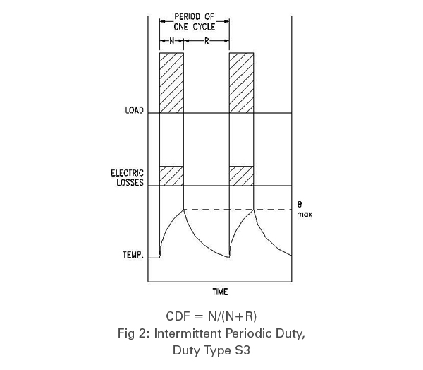
Intermittent Periodic Duty (Duty Type S3)
A sequence of identical duty cycle, each consisting of a period of operation at constant load & a rest period. These periods being too short to attain thermal equilibrium during one duty cycle. In this duty type, the starting current does not significantly affect the temperature rise. (Fig. 2)
Unless otherwise specified, the duration of the cycle is 10 min. The recommended values for the load factor are 15, 25, 40 & 60 percent.
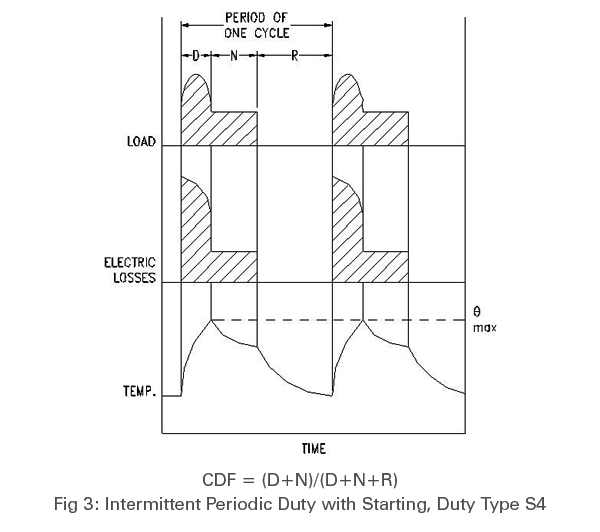
Intermittent Periodic Duty with Starting (Duty Type S4)
A sequence of identical duty cycles each consisting of a period of starting, a period of operation at constant load & a rest period. The operating, rest & de-energised periods being too short to attain thermal equilibrium during one cycle. (Fig. 3)
In this duty the stopping of the motor is obtained either by natural deceleration after disconnection of the electric supply or by means of braking such as a mechanical brake which does not cause additional heating of the windings
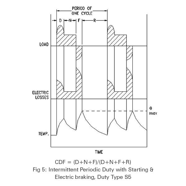
Intermittent Periodic Duty with Starting & Braking (Duty Type S5)
A sequence of identical duty cycles each consisting of a period of starting, a period of operation at constant load, a period of braking & a rest period. The operating, rest & de-energised periods being too short to attain thermal equilibrium during one cycle. In this duty, braking is rapid & is carried out electrically. (Fig. 5)
Note: In all the above type of duties, the loading duration & the idling duration of the cycle are so short that the steady state temp. is not reached. While working on these identical cycles continuously, the motor temp. rise must not exceed the permissible values.
APPLICATION
These motors are widely used in the following application:
DEFINITIONS
The terms frequently used in the intermittent duty drives are as follows :
FAQ & KNOWLEDGE BASE
In general these motors conform to the following standards:
| IS:325 | Three-phase induction motors specification |
| IS:4722 | Rotating electrical machines |
| IS:1231 | Dimensions of foot mounted A.C. induction motors |
| IS:2223 | Dimensions of flange mounted A.C. induction motors |
The formula to establish the rated output Pn in kW is
Pn >= (FxV)/(102 x eff) kW
Where
Pn .= (M x n)/ ( 974 x eff) kW
Where
The ratio of the period of energisation/loading, including starting and electric braking, to the duration of the one complete duty cycle expressed as percentage.
CDF = Period energised (Time for starting + Load + Braking) / Duration of one complete duty cycleGenerally the values for CDF used are 25%, 40%, 60%
PRICING
Contact us for more information on Crane Duty Motors or to discuss your requirements. Enquiries are solicited for India, UAE and Africa on following Email id web@aakashpower.com