Premium Efficiency Motor
- IE1 Standard Efficiency
- IE2 High Efficiency
- IE3 Premium Efficiency
- IE4 Super Efficiency
- Provides common international reference system for classification of motors
- Introduces new efficiency measurement method in conformity with standard IEC 60034-1-2: 2007 & IS: 12615 : 2011
- Single-speed, three-phase, 50 and 60 Hz
- • 2, 4, 6, 8-pole
- Rated output from 0.75 to 375 kW
- Rated voltage UN up to 1000 V
- Duty type S1 (continuous duty) or S3 (intermittent periodic duty) with a rated cyclic duration factor of 80% or higher
- Capable of operating direct online 50 and 60 Hz
- Method for determination of efficiency of IE2 & IE3 motors are based on IS: 12615: 2018 & IEC 60034-2-1
- Anti Condensation Heaters: for motors operating in damp locations: Motors can be provided with anti-condensation heaters for reliable operations in damp locations, condensation problems in motors can be avoided by maintaining a winding temperature 5 [degrees] C to 10 [degrees] C above the surrounding air temperature.
- Thermal Protection: Most of the motor failure contributors and failed motor components are related to motor overheating. Thermal stress potentially can cause the failure of all the major motor parts Stator, Rotor, Bearings, Shaft and Frame. PTC Thermistor acts as a thermal protection device for motors. A thermistor is a component that has a resistance that changes with temperature. There are two types of thermistor, those with a resistance that increase with temperature (Positive Temperature Coefficient – PTC) and those with a resistance that falls with temperature (Negative Temperature Coefficient – NTC). Generally PTC is used in Motors. When a given temperature is exceeded, the circuit can be switched off through a relay or amplifier, since the PTC-sensor will have an extremely high ohmic value in the region of its response temperature.
- Resistance Temperature Detectors (RTDs): RTDs (Resistance Temperature Detectors) are precision, wire-wound resistors with a known temperature resistance characteristic. In operation, the RTD is usually wired into a specific type of circuit (wheatstone bridge). The output of this circuit can be used to drive a meter which has been calibrated in temperature, or to operate a relay to sound an alarm or shut down the motor. The RTDs are installed in the slot portion of form wound motors, and either in the slot (standard) or in the end turns of mush wound motors. Bearing RTDs & the winding RTDs will have the same resistance value, so that the same monitoring equipment can be used.
Suppliers, Distributors, and Exporters of Premium Efficiency Motor
Aakash Power is a Global Supplier, Exporter, and Distributor of Premium Efficiency Motor, delivering complete motor solutions to the world’s most demanding industries. Our Premium Efficiency Motors are approved by the international set of standards.
INTRODUCTION
Efficiency of an electric motor is defined as the efficiency with which it converts electrical energy to mechanical energy.
It is a fact that motors consume 70% of energy in industry, therefore using high efficiency motors will result in huge savings & reduction in environmental impact.
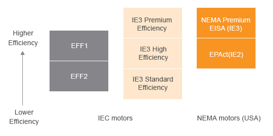
The demand for standardised efficiency led manufacturers to develop harmonised international standard and push the issue of IEC (International Electrotechnical Commision) Standard IEC 60034-30-1 & adopted in India as IS: 12615: 2011 efficiency classes for Single speed, three phase, cage induction motors.
This new standard defines new classes of efficiency
Table shows the correspondence among the main class
SCOPE OF SUPPLY FOR IE2 & IE3 MOTORS
CONSTRUCTION
Stator
Stator is a stationary part of induction motor.
A stator winding is placed in the stator of induction motor and the three phase supply is given to it.
For Premium Efficiency IE3 motor increased mass of copper on the stator enhances motor electrical efficiencies due to higher electrical conductivity.
The stator of the three phase induction motor consists of three main parts :
Stator Frame
It is the outer most part of the three phase induction motor. Its main function is to support the stator core and the field winding. It acts as a covering and it provides protection and mechanical strength to all the inner parts of the induction motor.
The frame is either made up of die cast or fabricated steel. The frame of three phase induction motor should be very strong and rigid as the air gap length of three phase induction motor is very small, otherwise rotor will not remain concentric with stator, which will give rise to unbalanced magnetic pull.
Stator Core
The main function of the stator core is to carry the alternating flux. In order to reduce the eddy current loss, the stator core is laminated. These laminated types of structure are made up of stamping which is about 0.4 to 0.5 mm thick.
All the stamping are stamped together to form stator core, which is then housed in stator frame. The stamping is generally made up of silicon steel, which helps to reduce the hysteresis loss occurring in motor.
Stator Winding or Field Winding
The slots on the periphery of stator core of the three phase induction motor carries three phase windings. This three phase winding is supplied by three phase AC supply. The three phases of the winding are connected either in star or delta depending upon which type of starting method is used.
The squirrel cage motor is mostly started by star-delta starter and hence the stator of squirrel cage motor is delta connected. The winding wound on the stator of three phase induction motor is also called field winding and when this winding is excited by three phase ac supply it produces a rotating magnetic field.
Rotor
For Premium Efficiency IE3 motor greater amount of conductor material enhances motor electrical efficiencies, this achieved by optimizing slots & increasing length of rotor. Thinner Lamination & greater silicon concentration helps reduce eddy current losses in the core.
The rotor is a rotating part of induction motor. The rotor is connected to the mechanical load through the shaft. The rotor of the squirrel cage three phase induction motor is cylindrical in shape and have slots on its periphery.
The slots are not made parallel to each other but are bit skewed as the skewing prevents magnetic locking of stator and rotor teeth and makes the working of motor more smooth and quieter. The squirrel cage rotor consists of aluminum, brass or copper bars
Shaft
The shaft steel material for standard motors is EN 8/ C45, in frames IEC 63 to 315S/M, and EN 24 for frames 315L, 355M/L. When supplied with roller bearings, the shaft material must be EN 24. Important: when equipped with a roller bearing, it is necessary to lock the non - drive end bearing which obliges replacement of the non - drive end bearing cap.
Shafts of motors are supplied with an open profile keyway, with a threaded centre hole, and can optionally be provided with a second shaft end. Dimensions of motor shafts are per IS: 325. Motors can also be supplied with EN24 or stainless steel shafts as specified by customer.
Bearing
Motors are supplied with deep groove ball bearings as standard. Optionally, for frame sizes 160 and above, NU series roller bearings can be fitted to motors intended for heavy duty applications where high radial loads may occur e.g. pulley and belt drives. The nominal bearing life is 20000 or 40000 hours in conformance with maximum radial and axial loads as described as per IS 12615:2018.
When direct coupled to the load (without axial or radial thrusts), the bearing life can be extended to 50000 hours. In standard configuration, with ball bearings, the drive end bearing is locked axially from frame 160. When provided with roller bearings, the non-drive end bearing is locked and the axial movement is compensated by the axial play of the front roller bearing.
The lifetime of the bearing is dependent on its type and size. Motors in IEC frames 200 and above are provided as standard with grease fittings in each end shield to permit the re lubrication of the bearings.
Motors can, on request, be equipped with bearing temperature detectors to provide continuous monitoring of bearing operating conditions. This type of monitoring is extremely important considering that it directly affects the grease and bearing lives particularly on motors equipped with re greasing facilities.
Cooling Fan
Reduced operating temperatures through optimized cooling system fan, fan cover & frame design contributes to energy saving & achieving consistent efficiency as per IE2 & IE3 standards
For TEFC squirrel cage induction motor, cooling air is usually circulated internally and externally by one or more fans mounted on the rotor shaft. To allow for operation of the machine in either direction of rotation, fans are usually of the bi-directional type and made of a strong plastic material or cast iron.
In addition, the external frames of the motor are provided with cooling ribs to increase the surface area for heat radiation. These are designed to keep the air flow close to the surface of the motor along its entire length, thus improving the cooling and self-cleaning of the ribs. An air-gap is usually left between the ribs and the fan cover for this purpose.
Internally, on smaller TEFC motors, the rotor end-rings are usually constructed with ribs to provide additional agitation of the internal air for even distribution of temperature and to allow the radiation of heat from the end shields and frame.
Mounting
All combination of Horizontal & Vertical Mounting are available for IE2 & IE3.
Terminal Box
The terminal box material is either cast iron or aluminum, depending on the motor type. The main terminal box is attached either on top, on side, or at a 45 degree angle on the side. It may also be connected to the motor with extended cables, so called flying leads.
In case of accessories such as thermistors or heating elements, one or more auxiliary terminal boxes may be attached to the motor. Non-standard designs of terminal boxes, such as non-standard size and degree of protection, are available as options.
A standard motor usually has six phase connections and at least one earthing connection. The necessary connection parts and a connection diagram are delivered together with the motor, under the terminal box cover The terminal box in aluminum motors allows cable entry from both sides.
In small motors, the box is integrated in motor frame and has a blind flange on with knockout openings on both sides (Figure 5.6). Larger aluminum motors are equipped with two connection flanges on both sides.
In cast iron motor sizes 71 – 132, the box is integrated in the frame, with connection on the right-hand side (viewed from the D-end). Sizes 160 – 355 have a terminal box that can be rotated 4x90°. The 4x90° turnable box is available as an option for several other motor types as well.
The degree of protection of a standard terminal box is IP 55.